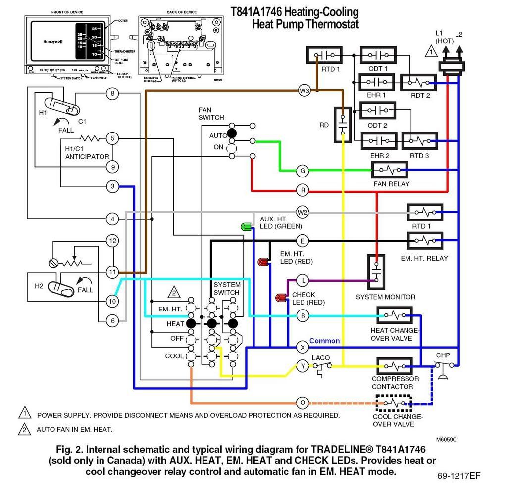
Thermostat Internal Wiring Diagram
Furthermore this thermostat wiring diagram is specifically for a system with two transformers your system likely only has one transformer as most typical residential systems only use a single transformer for control. L only connected if heat pump has a fault terminal.
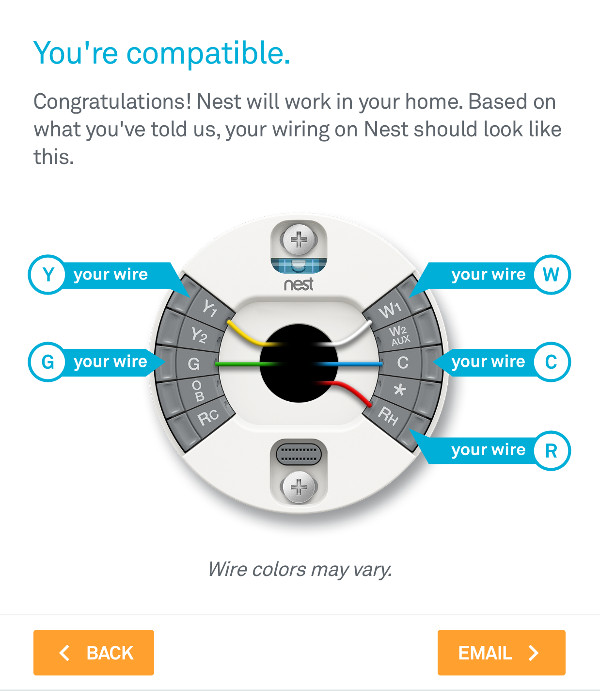
Nest thermostat Heat Pump Wiring Diagram Free Wiring Diagram

The thermostat is the control device that provides a simple user interface with the internal workings of your homes climate control system.

Thermostat internal wiring diagram. As shown in the diagram, you will need to power up the thermostat and the 24v ac power is connected to the r and c terminals. Some installers may use 20 awg copper thermostat wire. 1 heat / 1 cool thermostat.
Blue, green, red, yellow, white wires. Five conductor thermostat wire cables will include these colors: The color of wire r is usually red and c is black.
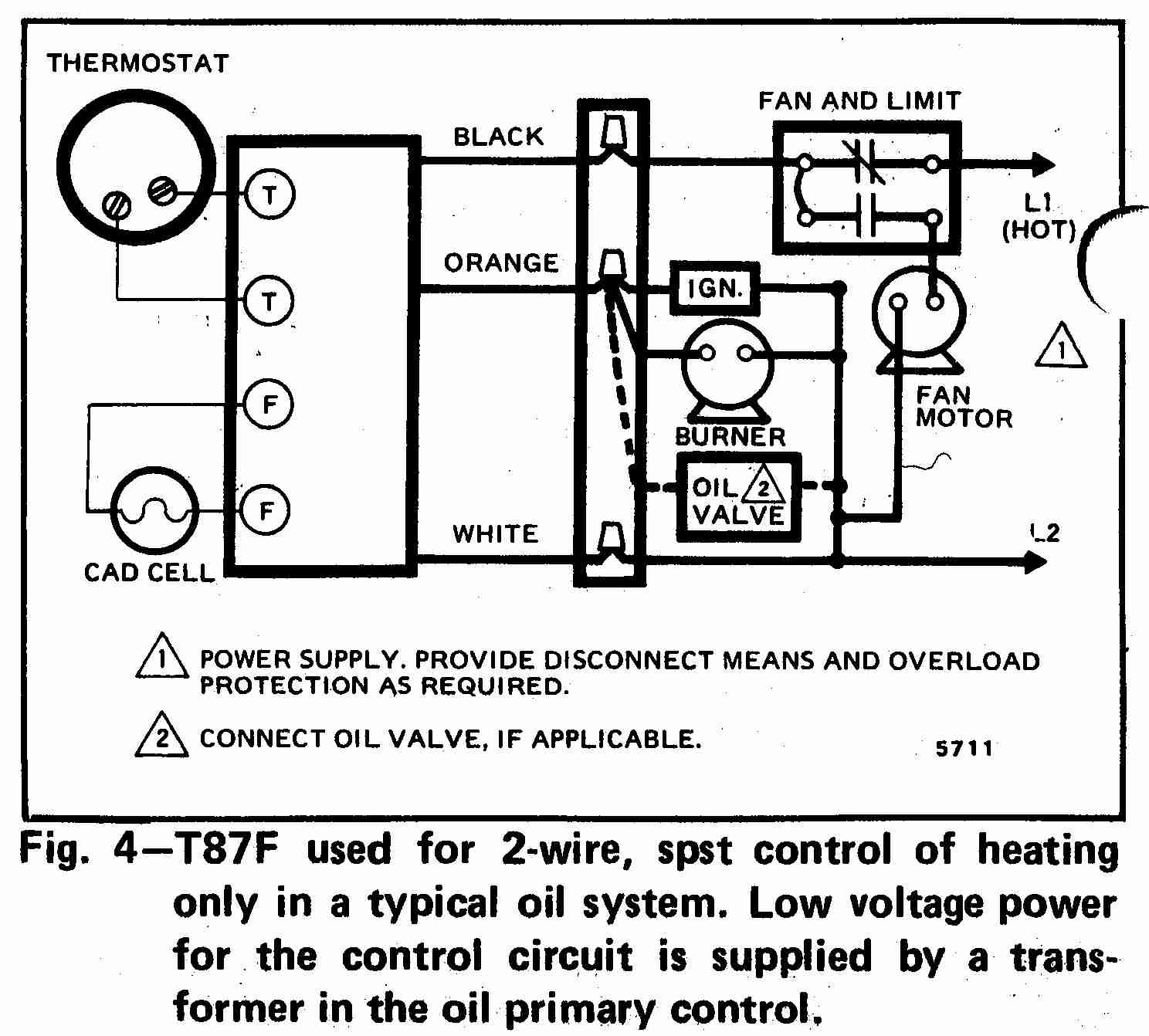
Heat pump thermostat wiring explained! Internal thermostat of the ck/cns heaters will turn off occasionally, even at their highest setting. Figure 1 is a circuit diagram showing the simplest possible known thermostat control system for heating and cooling operation of an a/c and furnace or a/c and electric heat system.
Thermostat wire used for heating and cooling systems is usually 18 gauge solid copper conductor, unshielded cable. If we put it simply, a 2 wire thermostat is one that has only 2 wires coming out of its backside. Furthermore, this thermostat wiring diagram is specifically for a system with two transformers.
Furnace and ac (color coded) 1 heat / 1 cool thermostat. Some heat pumps use b rather than o.solved: It doesn t control cooling and because it s a mechanical thermostat it doesn t need power for internal functions so it has no c wire.
This t stat also needs no c wire. It includes directions and diagrams for various kinds of wiring methods along with other items like lights, windows, and so forth. Wiring diagram consists of numerous in depth illustrations that display the relationship of various products.
The thermostat uses 1 wire to control each of your hvac system’s primary functions, such as heating, cooling, fan, etc. Wiring diagram for nvent nuheat thermostats terminals for the floor sensor are located on the nt side of the thermostat base not illustrated. Heat pump m 3h/2c heat pump with electric aux heat.
Your system likely only has one transformer, as most typical residential systems only use a single transformer for. Amp maimum per thermostat without use of relay switch For this system, you will notice that g (air handler blower) and.
See the diagram below for what each wire controls on your system: 1 heat / 1 cool thermostat. With this kind of an illustrative manual, you’ll have the ability to troubleshoot, avoid, and complete your projects without difficulty.
Ine from panel are copper ground nvent nuheat ground etal braiding nvent nuheat mats. The yellow wire connects to your. Wiring a 2 wire thermostat is pretty straightforward.
120 v heater with line voltage thermostat. *if using ibus method (function3 option2), connect the red wire to terminal r (12v acc). The nest thermostat is not only the best 2 wire wifi thermostat but it is one of the best wifi thermostats you can get for your home.
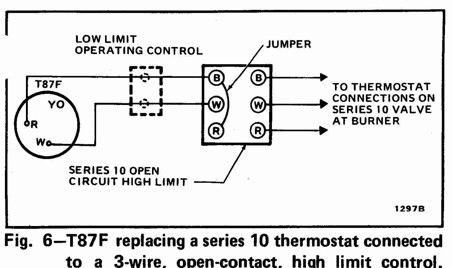
Honeywell mechanical thermostat wiring diagram. Again referring to the honeywell thermostat ct31a1003 wiring diagram you can see it requires only two wires r and w. See figures 1 and 2 for wiring diagrams illustrating the manner in
These two connections will ensure that there is power to the thermostat that you are. The red wire or 24 vac power lead is connected straight to the rc 4 terminals. 2 wire thermostat wiring diagram heat only.
C is known as the common terminal. Please use the following wiring diagram to connect thermostat mod into your car: Colors, terminals, functions, voltage path!
T6 pro wiring diagrams 5 —01 3h/2c heat pump with electric aux heat dual fuel, 2h/1c: Wires of the floor sensor go into terminals and d only no polarity.
Nest Internal Wiring Diagram Nest Wiring Diagram

Nest Internal Wiring Diagram Nest Wiring Diagram

Room Thermostat Wiring Diagrams For Hvac Systems Hvac Thermostat Wiring Diagram Cadician's Blog
Room thermostat wiring diagrams for HVAC systems
Nest Thermostat Internal Wiring Diagram Nest Wiring Diagram

Nest Thermostat Internal Wiring Diagram Nest Wiring Diagram

Can I provide a secondary power source for my thermostat? Home Improvement Stack Exchange

Want to replace thermostat but not sure what kind of system I have Community
19 Brilliant Danfoss Room Thermostat Wiring Diagram Images Tone Tastic

Nest Thermostat Wiring Diagram Uk Hack Your Life Skill
Nest Thermostat Internal Wiring Diagram Nest Wiring Diagram

Nest Thermostat Internal Wiring Diagram Nest Wiring Diagram

How To Install The Nest Thermostat The Craftsman Blog
Internal Wiring Diagram Of A Thermostat 27
Thermostat Wiring Explained

Robertshaw Thermostat Wiring Diagram DESSYAJAVIER
Nest Thermostat Internal Wiring Diagram Nest Wiring Diagram

Nest Thermostat Internal Wiring Diagram Nest Wiring Diagram

Wiring A Thermostat With 3 Wires / Three Wire Thermostat Wiring Diagram Wiring Diagram And
