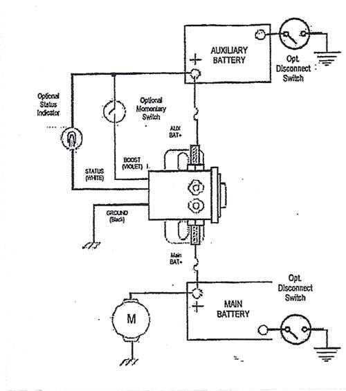
Sunpro Amp Gauge Wiring Diagram
After mounting the gauge, the wire from the ground source (step 4) should be connected Designed for 12 v negative ground systems, and includes 12 v internal lighting.
Sunpro Super Tach 2 Wiring Diagram Wiring Diagram
This is how i installed my ammeter in my nx2000 according to the directions sunpro included, they give you 8 different ways to install this gauge, you just have to find the correct diagram out of the 8 to install it right.

Sunpro amp gauge wiring diagram. Pin 1 u u / pur l. Sunpro gauges installation instructions keywords: Using 18 gauge wire, connect the (i) terminal to a switched +12v source.
Mount the gauge and attach the remaining end of the wire from step 7 to the ammeter connection post marked with a “+”. This arrangement is provided for easy reference when dealing with a circuit wired in this arrangement. Although sunpro produces a number of volt meters that look different, the process of hooking up the gauge is the same regardless of the external appearance.
Car gauges, car gauge kits, custom gauges, aftermarket car gauges, car performance gauges, gauge pods, digital gauges, air gauges, fuel gauges, oil pressure gauges, temperature gauges, performance gauges created date: In the automotive context, a voltmeter gauge displays the number of volts stored by the vehicle's battery. 8 to 18 volt range;
Sunpro amp gauge wiring diagram gauges circuit symbols o diagrams temp com voltmeter schematic auto block and 7 harness connector id locations. Gauges come in several different styles including white or black, dial face with chrome or black panels and bezels. I checked the gauge out and the metal housing was the part that was actually sparking.
Sunpro voltmeter wiring diagram ford truck enthusiasts forums equus digital. However, about a week ago i was driving and everytime i hit a bump sparks would fly from the back of the amp gauge. Amp gauge wiring 1) always disconnect the ground lead from the vehicle battery before wiring any gauge.
With this sort of an illustrative guide, you will have the ability to troubleshoot, prevent, and total your assignments without difficulty. Variety, either remove the fuse or disconnect one wire connection from the circuit breaker. The back of the amp gauge.
Each component ought to be placed and linked to other parts in particular manner. Sunpro gauges installation instructions author: Discussion starter · #1 · aug 22, 2005.
Pin 2 ol in u /blu. Sunpro fuel gauge wiring diagram wiring diagram is a simplified within acceptable limits pictorial representation of an electrical circuit it shows the components of the circuit as simplified shapes and the capacity and signal connections together with the devices. Check out our wiring wizard for step by step instructions videos and wiring diagrams including 3 way for installing a dimmer.
Fuel level gauge wiring (figure 4): In order to example wiring diagram. My 68 had sunpro gauges (amp,temp&oil) installed when i got it.
Up to 20% cash back 12. How to wire a sunpro mini tach 1984 ford f 150. 7) connect a good ground to terminal “g” on the back of the gauge (the ground is only used for the gauge light).
If not, the structure won’t function as it should be. An ammeter measures the amperage (volume of. From street racers to classic automotive enthusiasts, sunpro is dedicated to delivering.
It includes directions and diagrams for different kinds of wiring strategies along with other things like lights, windows, and so forth. Sunpro amp gauge wiring diagram. Wiring diagram consists of many detailed illustrations that show the connection of assorted things.
Attach one end of the wire to a clean ground source, such as a metal panel.sunpro ammeter wiring diagram posted by maria nieto in diagrams you can also find other images like wiring diagram, parts diagram, replacement parts, electrical diagram, repair manuals, engine diagram, engine scheme, wiring harness, fuse box, vacuum diagram, timing belt, timing chain,. There should be 4 colored wires coming out of the back of the tach. 2) classic instruments’ amp gauge should only be used on vehicles with alternators rated at 60 amps or the amp gauge was designed to be wired in series with the vehicles electrical system.
This wire should also be long enough to reach the voltmeter. 6) connect a minimum 10awg wire from the “+12v” terminal of the starter solenoid to terminal “i” on the back of the gauge. Includes gauge and mounting hardware.
Monitor alternator performance with the retro line 2 in. Good electrical connections are important for maintaining gauge accuracy and avoiding heat build up in the wiring. Sunpro offers a variety of mechanical and electrical gauges including oil pressure, oil/water temperature, voltmeter, ammeter, vacuum/boost, vacuum, fuel level and air fuel ratio.
In the diagram below a 2 wire nm cable supplies power from the panel to the dimmer box. 5) connect a minimum 10awg wire from the alternator “output” to terminal “s” of the amp gauge.
Sunpro Amp Gauge Wiring Diagram Diagram Sunpro Super Tach 2 Wiring Diagram Full Version Hd
Sunpro Amp Gauge Wiring Diagram Diagram Sunpro Super Tach 2 Wiring Diagram Full Version Hd
Sunpro Gauge Wiring Diagram Complete Wiring Schemas
Sunpro tachometer wiring Sunpro Super Tach Ii Wiring Diagram
Sunpro Gauge Wiring Diagram Complete Wiring Schemas
Sunpro Super Tach 2 Wiring Diagram Cadician's Blog
Sunpro Voltmeter Wiring Diagram
Sunpro Amp Gauge Wiring Diagram
21 Luxury Sunpro Super Tach 3 Wiring Diagram
Sunpro Amp Gauge Wiring Diagram
Sunpro Amp Gauge Wiring Diagram Diagram Sunpro Super Tach 2 Wiring Diagram Full Version Hd
Sunpro Amp Gauge Wiring Diagram SUNPRO Ammeter Gauge Kit Cp7981 for sale online eBay In
Sunpro Voltmeter Wiring Diagram
Sunpro Amp Gauge Wiring Schematic Wiring Library Sunpro Super Tach 2 Wiring Diagram Wiring
Sunpro Amp Gauge Wiring Diagram
Sunpro Tach Wiring Diagram New Tachometer Blurts Within Sunpro Tach Wiring Diagram Cadician
Sunpro Amp Gauge Wiring Diagram